Micro Controller Tutorial ...
Micro controller is the brain of robotics, Without this We cannot perfom even a single task from Robot. So Lets grab basic knowledge about controllers. I 'm going to given tute on the basic micro controller of Atmel At89c51 i.e. 8051 family. This is a 40 pin IC.
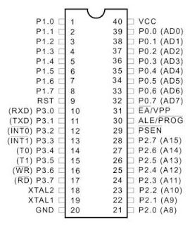
This Is the Pin configuration Of AT89c51 Micro Controller :-
There are 4 ports in this controller And Every Port has 8 Pins:-
1. Port 0 - Pins 39 to 32
2. Port 1 - pins 1 to 8
3. Port 2 - Pins 21 to 28
4. Port 3 - Pins 10 to 17
Port 0 :- Port 0 has dual function i.e you can send data or address on this port accourding to ur choice thats why there is written AD0, AD1 in the bracket."A" mean Address and "D" mean data here only. About these addresses and data you know when u learn assembly langugae. So this time just cram :P you can connect any device on this port like led , display,swicth etc..
Port 1 :- On This port you can connect any device you can send data according to your choice, like you connect led , switch etc ..
Port 2 :- On this port you can send address, rest function is same like other ports. mean you can connect any device or give any signal according to your requirement.
Port 3:- This Is really worthfull port , As you see on this port there is transmitter , receiver,interrupts,timmer,read/write signals. these rae really very valueable during programming.
Pin 20 (GND) :- This Pin is permanently connected to ground , it mean we given 0 potential at this pin.
Pin 40 (VCC):- At this pin 5V Supply is given. its the requirement of 5V, if we give more than 5V then it may damage or burn our Controller.So Only 5V is given from supply.
Pin 31 :- It is also connect to Vcc i.e. 5V supply. Its Active Low Pin it means if we given logic 1 externally then logic 0 gets in, mean that we give complement goes to that pin. Now We are given 5V at this pin mean logic 1, and due to active low 0 v mean logic 0 goes to this pin. Check the diagram you See the bar sign(-) on the "EA" this means active low, if there is no bar sign then it means active high.
Pin 18-19 (XTAL1-2) :- At this Pin the standard frequency Crystal is Connected, XTAL mean Crystal. For conecting Crystal there is proper circuit according to which you must make connection. From crystal frequency generates. eg:- Mostly 12 MHz(11.059Mhz )frequency crystal is used. check the different crystal diagram below.Mostly you see last 2 one in circuits.
Pin 9 (RST) :- RST mean reset, this is a reset pin where we can connect connect switch so that when we press our controller reset. mean start from intially.
Hope You Have Some Clearification About The Controller.
Regards,
Manan Saini ...


0 Responses to Micro Controller Tutorial ...
Something to say?