Hello Friends, Welcome For Visiting This Site .. This Site Is Under Construction ,Shout in the shout box if any doubt, Enjoy Robotics ... Cheers .!!
About This Site


Hello Friends, I make This Site For Robot Dicussion And for Tutorial On Robtics. If u Have Some Good Ideas Then Plz Post Here , Always Welcome You On This Site...

Never Hesitate To Ask Your Question , It will finish Your Thinking Power ...


So , " Think Beyond , Think Ahead "

Hope u Enjoy...

cheers !

Owner ...

SHOUT HERE ...

Hi Friends,

For 8051 family Burner i.e. programmer with the help of which we can burn or Program our micro controller . For this we need as well hard ware and software. IF you want you make it own hardware but it is bit complictaed for making PCB. because so many small cross tracks which gonnashort during PCB making. If u want to buy then u buy from his original site here :-

Buy Here

IF u Want to make its own then go for this :-


Features

  • Supports major Atmel 89 series devices
  • Auto Identify connected hardware and devices
  • Error checking and verification in-built
  • Lock of programs in chip supported to prevent program copying
  • 20 and 40 pin ZIF socket on-board
  • Auto Erase before writing and Auto Verify after writing
  • Informative status bar and access to latest programmed file
  • Simple and Easy to use

Specifications

Dimensions: 76mm x 180mm (3" x 7")
Power Supply: 14-18V DC or 12-16V AC
Interface: RS-232, 9-pin D connector
Data Speed: 57600 bps, 8 bits, no parity, 1 stop, no flow control
File format: Intel 8-bit HEX
Program Sockets: 40 pin DIP - 0.6" & 20 pin DIP 0.3" ZIF socket
Software: Works on Windows 95, 98, Me, 2000, NT, XP

Introduction

Simple to use & low cost, yet powerful flash microcontroller programmer for the Atmel 89 series. It will Program, Read and Verify Code Data, Write Lock Bits, Erase and Blank Check. All fuse and lock bits are programmable. This programmer has intelligent onboard firmware and connects to the serial port. It can be used with any type of computer and requires no special hardware. All that is needed is a serial communication port which all computers have.

All devices have signature bytes that the programmer reads to automatically identify the chip. No need to select the device type, just plug it in and go! All devices also have a number of lock bits to provide various levels of software and programming protection. These lock bits are fully programmable using this programmer. Lock bits are useful to protect the progam to be read back from microcontroller only allowing erase to reprogram the microcontroller.

The programmer connects to a host computer using a standard RS232 serial port. All the programming 'intelligence' is built into the programmer so you do not need any special hardware to run it. Programmer comes with window based software for easy programming of the devices.


Supported Devices

The table below shows the key differences between the various microcontrollers. Data sheets for each device can be found on the Atmel web site. All these devices are supported by the programmer.


Flash (Kbytes)EEPROMRAM (Bytes)I/O Pins
AT89C55WD20
25632
AT89C514
12832
AT89LV514
12832
AT89C528
25632
AT89LV528
25632
AT89C5520
25632
AT89LV55 20
25632
AT89S51 4
12832
AT89LS51 4
12832
AT89S52 8
25632
AT89LS52 8
25632
AT89S53 12
25632
AT89LS53 12
25632
AT89S8252 82 Kb25632
AT89LS8252 82 Kb25632
AT89C1051 1
12815
AT89C2051 2
12815
AT89C4051 4
12815


These microcontrollers from Atmel use flash memory to store programs. Flash memory can be electronically erased and programmed, no need for a UV eraser.

Programming Software

Computer side software called 'ProLoad' is executed that accepts the Intel HEX format file generated from compiler to be sent to target microcontroller. It auto detects the hardware connected to the serial port. It also auto detects the chip inserted and bytes used.


Connects to your computer's serial port (Comm 1, 2, 3 or 4) with a standard DB9 Male to DB9 Female cable. (Cable Included). Baud Rate - 57600,COMx Automatically selected by window software. No PC Card Required. Uses Intel Hex Data Format (Default output of most assemblers and compilers.)

Download Complete Package Here :-

1. Software Proload V5.4

2. Schematic

3. DIY PACK


Regards,

Manan Saini ...
 

Micro Controller Tutorial ...

Posted In: . By Manan Saini

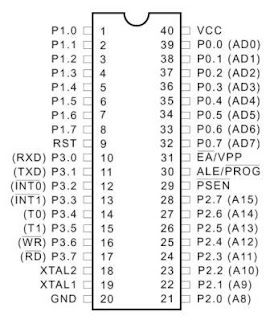
Micro controller is the brain of robotics, Without this We cannot perfom even a single task from Robot. So Lets grab basic knowledge about controllers. I 'm going to given tute on the basic micro controller of Atmel At89c51 i.e. 8051 family. This is a 40 pin IC.

This Is the Pin configuration Of AT89c51 Micro Controller :-

8051 Micro Controller Pin Configuration


There are 4 ports in this controller And Every Port has 8 Pins:-

1. Port 0 - Pins 39 to 32

2. Port 1 - pins 1 to 8

3. Port 2 - Pins 21 to 28

4. Port 3 - Pins 10 to 17


Port 0 :-
Port 0 has dual function i.e you can send data or address on this port accourding to ur choice thats why there is written AD0, AD1 in the bracket."A" mean Address and "D" mean data here only. About these addresses and data you know when u learn assembly langugae. So this time just cram :P you can connect any device on this port like led , display,swicth etc..

Port 1 :-
On This port you can connect any device you can send data according to your choice, like you connect led , switch etc ..

Port 2 :-
On this port you can send address, rest function is same like other ports. mean you can connect any device or give any signal according to your requirement.

Port 3:-
This Is really worthfull port , As you see on this port there is transmitter , receiver,interrupts,timmer,read/write signals. these rae really very valueable during programming.

Pin 20 (GND) :-
This Pin is permanently connected to ground , it mean we given 0 potential at this pin.

Pin 40 (VCC):-
At this pin 5V Supply is given. its the requirement of 5V, if we give more than 5V then it may damage or burn our Controller.So Only 5V is given from supply.

Pin 31 :-
It is also connect to Vcc i.e. 5V supply. Its Active Low Pin it means if we given logic 1 externally then logic 0 gets in, mean that we give complement goes to that pin. Now We are given 5V at this pin mean logic 1, and due to active low 0 v mean logic 0 goes to this pin. Check the diagram you See the bar sign(-) on the "EA" this means active low, if there is no bar sign then it means active high.

Pin 18-19 (XTAL1-2) :-
At this Pin the standard frequency Crystal is Connected, XTAL mean Crystal. For conecting Crystal there is proper circuit according to which you must make connection. From crystal frequency generates. eg:- Mostly 12 MHz(11.059Mhz )frequency crystal is used. check the different crystal diagram below.Mostly you see last 2 one in circuits.


Pin 9 (RST) :-
RST mean reset, this is a reset pin where we can connect connect switch so that when we press our controller reset. mean start from intially.

Hope You Have Some Clearification About The Controller.


Regards,

Manan Saini ...


Integrate Circuit's ( IC's )...

Posted In: . By Manan Saini

Integrated Circuit's (IC's) ...

Integraed Circuit Is Commonly Named As IC's ... I think you hear this term so many times , but not familier with this:) Here I will give breif introduction about IC's ...

First Ic made By texas instrument in 1958. With the help of one single ic we can perform number of task , no need to large number of transistor, diode ,resitor etc... This is the part of nano technology.


U hear the name of transisitor and vaccuum tubes, vacuum tubes are fitted in our old TV's . If u ever open ur very old tv u can see Vacuum tubes. They are very noisy and large devices and also produce so large heat. That is why IC's Invention comes.:)

One day in late July, Jack Kilby was sitting alone at Texas Instruments. He had been hired only a couple of months earlier and so he wasn't able to take vacation time when practically everyone else did. The halls were deserted, and he had lots of time to think. It suddenly occurred to him that all parts of a circuit, not just the transistor, could be made out of silicon. At the time, nobody was making capacitors or resistors out of semiconductors. If it could be done then the entire circuit could be built out of a single crystal -- making it smaller and much easier to produce. Kilby's boss liked the idea, and told him to get to work. By September 12, Kilby had built a working model, and on February 6, Texas Instruments filed a patent. Their first "Solid Circuit" the size of a pencil point, was shown off for the first time in March.


But over in California, another man had similar ideas. In January of 1959, Robert Noyce was working at the small Fairchild Semiconductor startup company. He also realized a whole circuit could be made on a single chip. While Kilby had hammered out the details of making individual components, Noyce thought of a much better way to connect the parts. That spring, Fairchild began a push to build what they called "unitary circuits" and they also applied for a patent on the idea. Knowing that TI had already filed a patent on something similar, Fairchild wrote out a highly detailed application, hoping that it wouldn't infringe on TI 's similar device.

All that detail paid off. On April 25, 1961, the patent office awarded the first patent for an integrated circuit to Robert Noyce while Kilby's application was still being analyzed. Today, both men are acknowledged as having independently conceived of the idea.


Modern Ic :-


Now the part comes function of different pins and how we identify :-

1. First how we identify the Ic name :-

Lets take the example of this Ic :-


Here it is written " D8086"

Every word has its own meaning :- this is a Ic number 8086 , for this time forgot all other things because for remebering its need lot of practice , now try only find the ic name :)

second thing here it is written:- " Intel 1978" mean it is made by intel in 1978 , but this thing is not written on every Ic.

Lets take another example For better understanding:-


Here written " LM 555 CN" , meaning the name of this IC is 555 and the meaning of LM is depend upon consturcion company every company has its own resgistered code name. and "CN" it tell about the packaging part of IC , Like P for plastic packaging.

For ur knowledge This IC is Commonly Known As 555 Timer.

As i already told u for the time only try to find the IC name Forgot rest thing:).


2. How To Identify Pin Number :-


Take the example of 555 IC , I think figure is fully explained by it self :-
Follow these steps :-

1. Check the Cut on the outer body of Ic , it is of two typemay be like circle as shown in figure or like a "U" shape like in new IC's.

2. set the postion of IC such that cut comes on the left side:) T fig as reference..

3. now start reading the pins in the series as in figure ie. below the cut it is Ist pin and so on ... when one side pins end then start the counting just opposite to side and countinuously go on...

Hope now u understand how count IC Pins. :)


3 Identify The Function of Pins :-


After You identify the pin number , now ques is what is the function of Pin1 ,2 ,3....

these function u will know from Data sheet of IC , that u found on internet just search it like " Data sheet of 555 " and check the variuos functing of diffeent Pins.


These three things are sufficent for using the IC :)

Hope u understand all the above:) if any problem just ask :) I make this tutorial by consider that u dont know anthing About such things(IC's) . So it be very simple as it can do:)

Gud Luck!


Regards,
Manan Saini ...


Obstacle Avoider Sensor...

Posted In: . By Manan Saini


IR Proximity Sensor Module :-


The IR proximity sensor module is based around the TSOP sensor, commonly used in TV remote receivers. This module is able to detect objects at a distance of 5cm to 15cm. The maximum detectable distance varies in accordance with the color and texture of the object. For example, a white object can be easily detected from a distance of 15cm while a black object would be detectable from a maximum distance of 5cm.

Tuning the obstacle detection module:-

You need the power supply/battery, controller board, IR proximity sensor module and a screw driver.

The sensors can be tuned so as to change the maximum detectable distance. This can be varied by changing the intensity of the IR emitter.

Step 1: Connect you module to one of the sensor port on the iBot controller. Refer the adjoining figure for reference.

Step 2: Turn on the power supply of your iBot controller.


Step 3: With the help of a screw driver, turn the potentiometer in such a way that the indicator LED just turns off. (if its already turned off, skip this step)


Step 4: Place an object (non-black) in front of the module at a distance of about 10cm and turn the potentiometer such that the indicator LED just lights up. This step makes sure that the same object would always be detected at a maximum distance of 10cm.

Similarly, you could move the object and turn your potentiometer to achieve an optimum distance.


Specifications:

Operating Voltage: 5Volts

Current Consumption: xxmA

Detectable distance: 5cm to 15cm


NOTE: IR light is invisible to the human eye but digital cameras like webcams or cell-phone cameras are capable of detecting it. Point your camera towards the IR emitter (while turned on) and see for yourself! This is a very handy debugging tool.


Source :- Tri Bot


Regards:-

Manan Saini...


Line Sensors ...

Posted In: . By Manan Saini

The line sensing module :-


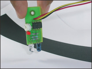
The line sensing module is designed to detect a white line on a black surface from an ideal distance of 10mm to 20mm. The module detects the line by measuring the intensity of reflected Infrared (IR) light. The sensor can be tuned to detect various contrasts, say white line on a green surface or a white line on a black surface.

The red indicator led lights up whenever in encounters a reflecting surface (white line)


Tuning the line sensing module:-

You need the power supply/battery, controller board, sensor module and a screw driver.

Step 1: Connect you module to one of the sensor port on the iBot controller. Refer the adjoining figure for reference.


Step 2: Turn on the power supply of your iBot controller.

Step 3: Place your sensor at a distance of approximately 2cm above the surface that you “don’t” want to detect, eg., a black surface.

Step 4: Using the screw driver, turn the potentiometer in either direction. You will notice that the indicator LED lights up at a particular point and goes off at another point. Now, in order to properly tune to the sensor, you need to turn the pot to such a point that the LED just turns off.

Step 5: Now when you place you sensor on a reflective surface (such as white) you’ll see the indicator LED glows. That’s it! We now have our Line Sensing Module all tuned up!


Specifications

Input Voltage: 5Volts

Optimum detecting distance: 10mm


Source :- Tri Bot


Regards:-

Manan Saini...


Contact Us

Posted In: . By Manan Saini

Hi Friends ,

For Contact Us Feel Free To click Here ...


1. Orkut Profile


2. Our communities :-

KRP


Or

3. Email Us


Different Parts Of Robot ...

Posted In: . By Manan Saini

First For Making Robot What things we Need :-

1. Discreate Components( like resistor , inductor , capacitor ,Transistors,Led's etc )


2. Sensors


3. Ic's (Microcontrolls)

Top View :-


Pin configration:-


4. Wheels


5.Motors


6. PCB (Printed circuit board) - On which our robo circuit is there ...


7. Battery / Charger :P

Nickel Battery Pack (rechargable) :-


8. Wires


9. Chassis (outer body of robo u can say cover)


10. Miscellaneous ( IR detector, Switches, Ports, Material For extra Finishing :P)

IR detector:-


Switches:-


Ports:-


Look here Some Pictures Of robots :-

Line Follower Robots :-

Bottom View :-

Top View:-


Regards:-

Manan Saini


Join This Community On Orkut :-

Join This Community On Orkut :-
KRP